Sunday, November 19, 2017

more successes

Next thing to do was cut something with multiple depths. Eventually I'd like to make some keychains for gifts and myself and family (well most of us) are Packers fans. So I grabbed this model off of Thingiverse and imported the STL into Fusion. I converted Mesh to BRep and scaled the model to fit the stock I was planning to use.

I set up the CAM for 4 operations (settings shown are the ones I converged on after 2 failures)

  1. Adaptive clear the interior
    • 1mm depth per pass
    • 250mm/min feed
    • 0.2mm stock left radially
  2. 2D contour the G
    • 0.5mm roughing depth
    • 120mm/min feed
  3. 2D contour the inner part of the outer ring
    • 0.5mm roughing depth
    • 120mm/min feed
  4. 2D contour the outer part of the outer ring
    • 0.5mm roughing depth
    • 120mm/min feed

I used a 1/8" 2 flute end mill at 2500rpm.

The first attempt, I broke an end mill entering the first 2D contour. I initially add a 1mm depth per pass on the roughing and it dug in and broke right away. I measured after the cut and it was actually 1.5mm deep! Z must have slipped, and admittedly I had "0" set a bit low, in that the first move across the part cut a channel about 0.2mm deep.

Second attempt I dropped the roughing depth to 0.5mm and set zero on the Z axis by setting the end mill on a razor blade on top of the part. This left it slightly shallow but I wanted to be careful. This worked much better, but I finally did break and end mill on the final contour. This was caused by 2 factors. One, once again the end mill dug in, secondly the part was not perfectly flat. Thirdly, perhaps somewhat contributing, is that I didn't have the center of the cut aligned so the outer 2D contour left the stock and re-entered. I think the combo of unloading, reloading, and having too deep a cut did me in. The cut was 1.mm on that side and 0.8m on the other. You think you'd see that but I swear the stock was flat! Combo of using a diced-up part as a shim and getting swarf between the milling vise, shim and stock.

Anyways the Z digging was an obvious common culprit that needed to be addressed. When I have a problem I can't figure out I generally do one of two things. The first? charge ahead and just start doing stuff and generally screw up a lot and get frusturated. The other, rarely, walk away do something else and then find a eureka moment. Fortunately this was one of the rare times - I had my commute bicycle partially torn apart to fix something, so I worked on that awhile and eureka. I was thinking about the GRBL settings and recalled that the X and Y have 126 steps/mm or something like that and the Z has a mere 25 steps per mm because I'm using an 8mm lead screw with direct drive. So it only takes a few missed steps to make a notable impact in the Z whereas in the X and Y I can lose a few and never know it. So, what if I enabled microstepping? A 1/4 step would give me 100 steps/mm and would be the same order of magnitude as the other axes. Sure, it masks a problem, maybe, but it 'scales' the problem to be the same order of magnitude as the other axes.

Third try - success! Code ran to completion, no broken end mills, and the dimensions were good to within 0.1mm or so - again, 10 steps, but margin of error, that's 4 thou which is pretty damn good if you think about it, for a mini mill with printed parts!

I did get some wicked backlash in the Y axis - the screws came loose on the affixing print. I need to add some threadlocker.

Saturday, November 18, 2017

First real part off the mill...

So I've finally got a part to run to completion! It's not the x-axis part I was making last weekend. I decided to give up on that for two reasons (1) it is a large piece and (2) if anything the printed x axis is the least weak part of the system. I have a bunch of aluminum cutoffs I scavenged ( ~ 50mm x 150mm x 5mm) so I made a smaller part. It's a spinning weapon from one of my kids' combat robots, scaled down by 50%.


This lovely weapon is then attached to a 2822 brushless outrunner and spins at about 7k RPM. It slices, it dices, it kicks other bots out of the arena!


Here's the first attempt. First g-code to run to completion! There are four, 1mm high tabs to hold the part to its stock to prevent flyoff. You can see there is a thin layer of aluminum between two of the tabs, clearly the stock is not flat or the head not perfectly trammed. 


The part tore out easily. I used a decomissioned pair of wire cutters to trim the flashing then a rough diamond file. Careful eye can see a fair bit of backlash in the larger holes and a dimple (due to backlash) on the bottom curve.


So back to the machine. Fiddled around with a number of things and found two things I thought were culprits. The first was play in the y-axis - I fiddled around with my printed housing for the motor and the bolts, and they were a bit loose. I did this on purpose at first because when I tightened everything down the axis became very hard to turn, likely because the print is slightly misaligned which shifts the housing around the shaft out of center. I took the housing apart and drilled out the bolt holes a few mm wider so that the print could slide around laterally. This helped quite a bit - I could lock down the print and the tension only increased a little bit over being loosely coupled. Secondly I tightened a few of the set screws in the saddle - again, to the point where it felt a little harder to turn, but not completely locked down. I also slowed down the Z axis a bit - some testing I was doing mid-week showed slips in the Z over time. I wanted to make sure I wasn't driving down the end mill too quickly and either moving the part or sucking the part up.

This one turned out much better. tolerance on the outer holes is ~0.15mm. The interior hole is about 0.05mm average narrower than the CAD. Which may make sense. In Fusion 360 I have the tolerance set to 0.1mm, and when you are adaptively milling out a hole you are essentially milling concentric circles. If you discretize a circle you get a polygon with a lot of sides, which is inscribed the circle, so perhaps this outcome is a-o-k. I need to study a little more to make sure my intuition is correct.


Anyways, super happy to have a part come off the mill. Repeatability in the Z axis is a bit of a concern and rebuilding the Z axis in metal is likely the #1 priority. 

Sunday, November 12, 2017

metal chips


Well, I almost made my first part. Almost.

I bought some cheap 1/8" two flute end mills from Amazon. 10 for $11. I am actually quite happy with them. As you might recall when I was cutting wood, with the 1/4" end mill I had I could cut out the big void in the middle and the perimeter, but the 1/4" end mill was too large to make the bolt holes and socket cap pockets. These end mills do the trick, and I only broke one in the process of making those bolt pockets.

I used adaptive clearing, setting a boundary of the outside of the part, with these settings it was able to clear all the holes with the 1/8" end mill. I omitted the center circle because man, that would take a long time to adaptively clear all that material! Here is the adaptive settings I used for the bolt holes and socket cap pockets:
  • Under Linking, section Ramp, set minimum ramp diameter to 1mm. This will allow you to mill out a pocket of (end_mill_diameter + 1) 
  • Turn off rest machining and ensure it isn't leaving extra stock
  • Change the optimal load to 0.75 (reduces loading, prevent snapping)
  • Make depth of roughing cut 1mm
  • Set "Order By Area" to ensure it finishes one pocket before moving to the next one - otherwise it will do all pockets at 1mm depth, then all pockets at 2mm depth, etc... 
  • Adjust speeds. I chose 250mm/min travel speeds, with my mill running at ~ 2000 RPM. If you have a router going faster, you can travel faster
I then set up a separate adaptive clear for the large center hole, and a 2D perimeter cut with tabs. For these I set up a 1/4" end mill. I managed to snap several of the 1/8" end mills trying to do 2D perimeter tests and gave up on that idea for today. It would successfully make a few passes, then bind and snap. I have some culprits (the Y axis is still sloppy, maybe it lets the bit drift and bind). But I figured sooner or later I'd have to entertain tool changes, why not start practicing now. 

Code set up, I kicked it off with ChiliPeppr. I had a few stumbles (y axis grub screws came loose, y axis end nuts came loose - I locktited them) but once I was cutting reliably in scrap aluminum it was time for a clean sheet.


The four bolt hole with socket cap pockets and the two thru-holes cut excellently. The tool change triggered. This part was nerve wracking but turned out to be no big deal. The steppers lock in place and so long as you drive with the GUI you can raise the head up, do your tool change, and drop it back down no problem. Which I did! Once you drop it back make sure you measure the position of the tool relative to the part. You can drop it to zero, align the tool on top of the surface, and tighten up. Resumed the code - a it did wind up binding up on the second pass - the X axis stumbled a bit and the bit gummed up and I killed it. I should have had the RPMs set higher on the spindle. DAMN. What to do.

Well, I decided to generate new GCode which just has the center adaptive clear and the perimeter cut. Instead of referencing the corner of the part, I referenced to the center of the circle. Using a compass, it is easy to find the center of the circle as the starting point. This went well, clearing out the middle pocket, but then it bound up on the second pass of the perimeter. I was using the same feed and speed as the adaptive clearing, but the adaptive clearing only loads about half the tool, whereas the perimeter cut is loading the entire tool. I should have the spindle going faster, or the tool going slower, or take a shallower cut. 

The other culprit is the slop in the Y axis. As it is going along the channel it can drift back and forth and suck itself laterally while still being driven, and potentially gum up the works because the channel depth of cut is deeper than the direction it is being driven.


So close, and yet so far away....

Next thing I am going to do is fix the Y axis coupler, before trying again. But regardless, videos below:


Saturday, November 11, 2017

Full power

So cutting wood, I noticed that the Y axis stepper motor in particular felt underpowered. It seemed to stall out without a whole lot of resistance and when I had the steppers locked in place it sure didn't feel like 400 oz-in of torque!

At first I blamed sticktion, then I blamed the Oldham coupler locking up at certain rotations. But I could get the handwheel to rotate smoothly, and there wasn't an excessive breaking force to get the axis spinning. 

So I did what any rational person would do, I grabbed the food scale out of the kitchen (sorry, wifey) and pushed on the handles of the Y axis handwheel while the stepper was locked and sure enough, I got something just under 200 oz-in of torque! What gives? I figured even if overadvertized, the steppers would at least be north of 300 oz-in, and I knew the motor drivers were sufficiently powerful to give me most, if not all of the advertised torque. 

So was it the motor or the drivers? Turns out it was the latter. The DRV8825 stepper driver board comes with a potentiometer to limit current. If you visit the pololu page for the DRV8825 stepper board, and scroll down to the video, you can watch a nice lady explain to you how to adjust the potentiometer. Not mentioned in the video: as shipped they limit to 1A current. The drivers are rated for 2.2A peak, 1.8A continuous. I set mine to 2.0A by setting VREF to 1.0 volt. 

A little more information: The 2 amps is per coil. The steppers are rated to a peak of 2.83A for the motor - not for the coils! If you are treating the motor as bipolar (by wiring the four coils as two sets in series) the maximum current would be the square root of 2 amps, squared, for each coil, which works out to 2.83 amps. Or 2 amps per coil. So set the motor drivers to 2 amps knowing you aren't exceeding the capability of the motor. You do need to ensure you aren't microstepping - on my board you need to explicitly set a sequence of jumpers to enable microstepping. 

One other thing to note: while bipolar series has more holding torque than bipolar parallel, bipolar parallel has more torque at speed than bipolar serial, however it draws more amps - need a bigger motor driver. See the "series v. parallel" figure towards the end of this article.

Making sawdust

So with the X, Y and Z axes in existence (note: nowhere near complete or dialed in) its time to make some wood chips. A bunch of 2x4 ends donated from a woodworking neighbor are a bit more failure-tolerant than aluminum. 

In action. Had to deal with a couple slips in the Y axis. I had the most mental anguish about the Z axis, but in truth the Y axis is more of a pain in the butt than the Z is ... 


I took the CAD for the X-axis plate since it was the simplest and played in Fusion with the adaptive clearing. The bolt pockets are too small for my 1/4" end mill but the center hole and outline work fine. Obviously in a real part you wouldn't clear a full square around the part - I need to figure that out (probably use adaptive in the part, 2D cut outside?)


Watch the wood chips fly for yourself!


Z axis

I'm a couple weeks late posting this - as they say, life comes at you fast. 

My original projection for getting the CNC operational was "1 week for X, 2 weeks for Y and 3 weeks for Z, cut a meaningful part by Thanksgiving (week 9)". And I came in right on time. I had the Y axis operational week 2 but took another week to re-work it properly, and after a false start week 5, I got Z operational on week 6. 

The setup is pretty simple. A stepper motor is cantilevered over column to drive a leadscrew that is between the machine head and the column. A thrust bearing on the bottom supports the load through the leadscrew, and an adapter holds the leadscrew nut to the head.

First things first, head needs modifying to provide a gap between the column and the head. If you flip the casting over there are three webs that extend across the casting (highlighted in red below). I had a buddy of mine from work who converted his mill to CNC take those down ~ 15mm. This allowed sufficient gap to run the leadscrew down the head once the rack and pinion were removed.


Without the spring lift the head wants to drop (gravity is a harsh mistress) and so I made a print that encompasses the bottom of the head casting and bolted the leadscrew nut to it. In the picture below it is the black plastic part which wraps around the bottom.


Although in practice gravity might not be enough, the head can still try to jump - may add an air spring pushing down to force the head down even against upwards pressure from a translating cut. For now you can see a clamp is holding it in place.

As mentioned the motor is mounted cantilevered off of the column. I printed an adapter 10mm thick with a 10mm extension going into the headstock. This does wiggle a bit here and there, it should be made of metal once I can. The printed part could be improved by having a 30-ish-mm extension going into the column and using several exposed bolt holes to secure in place.


Another view showing the coupler I made on the lathe. It was a 1" diameter bar stock turned down to ~18mm to clear the head when it slides up over it. Several tapped holes with grub screws secure the motor shaft to the leadscrew.


Thrust bearing. The metal part on top of the thrust bearing is made on the lathe, it fits inside the thrust bearing and has a hole to accomodate the leadscrew. It can then spin freely against the thrust bearing sitting atop the hard stop. I put a reasonable amount of force into driving the hard stop against the leadscrew when securing in an attempt to carry most the weight - I don't want to wear out the steppers' bearings. An alternative construction I am considering is putting the thrust bearing up top annd hanging it instead of supporting from the bottom.


The mill with all 3 glorious axes.


Cheap 48v adjustable power supply. Black box houses the Arduino with the CNC shield.


Final setup with T-shirt chip baffle!


Chips will fly, soon! Printed parts can be found on thingiverse.

Sunday, October 22, 2017

Controller configuration

For initial testing, I would take my laptop out to the garage and use Grbl-Panel.


Slick as Grbl-Panel is, I don't relish ingesting a chip into my laptops' keyboard. So I am going to use an Orange Pi Lite as a grbl server. Prior to the advent of the Raspberry Pi 3, the Orange Pi devices were half the cost and came with integrated wifi, and had more powerful processing power - while the latter is no longer true they are still cheap, nearly expendable computers. I'm not sure the exact configuration I'll end up with but I have had 3 ideas

1. Get a Raspberry Pi touchscreen and go full touch interface.
2. Get cheap used DVI monitor/keyboard/mouse and use the OrangePi as a computer interface
3. Use server software and jog via tablet/upload gcode for production

I'm going to go with (3), with (2) as a backup. During testing I can use my cheap windows tablet as a pendant and during production runs I dont need to have any computer there except the Orange Pi. If this is limiting I'll add a monitor/keyboard from the thrift shop.

Orange Pi Configuration

I installed a fresh Armbian image, added my user acoount and enabled wifi (nmcli c up id <router name>).


First things first: perform an apt-get update, apt-get dist-upgrade to ensure the latest packages. Reboot and make sure your wifi configuration sticks.

First program I tried was grblweb. This is a nodejs-based program that allows you to control your mill remotely through a web browser. It looks fairly simple and well thought-out, the only downside to the naked eye is that github hasn't been updated in 2+ years.

Clone it from github:
 git clone https://github.com/andrewhodel/grblweb

grblweb is built on nodejs, so we need to install nodejs/npm and various dependencies:
 sudo apt-get install nodejs npm
 sudo ln -s /usr/bin/nodejs /usr/bin/node
 npm install serialport
 npm install socket.io
 npm install node-static

now you should be able to cd into grblweb and execute
 node server.js

Load up a web browser to the IP of the machine, port 8000 and you should see the GUI.

If you want to run it as a service (start on boot) you can use forever and crontab. First install forever
sudo npm install forever -g (g=all users) Then follow the instructions from the top answer at stackoverflow.

I went out in the garage to test. I was able to jog the mill with the graphical joystick on my laptop but this was problematic on my tablet - sometimes it would be interpreted as moving the screen, other times as a joystick jog. Additionally there weren't a whole lot of features to do interactive positioning or gcode playback. I was a bit disappointed - this is probably great for production use but I needed something more oriented towards diagnostics.

So I went to the backup plan - ChiliPeppr. The concept is that ChiliPeppr is a "hardware fiddle", a more-or-less generic gui for various hardware devices. By forking the code and creating workspaces, you can create interfaces for new devices. Among these devices are grbl devices. NOTE: if you are using Grbl 1.1 (ie: the latest release) you want to use this workspace, not the grbl one which supports 0.9. In order to talk to your mill you need to download the JSON server for your computer (arm in our case) (download link bottom-right part of screen) and start the service on the Orange Pi. Now with any other device on your network you can connect to your device (bottom-right) using a URL that looks like ws://192.168.1.10:8989/ws. Your device will show up. Before connecting, you must change the connection type dropbox to GRBL! This will cause confusion if you do not. Click the checkbox next to the arduino and you're connected. You can jog by clicking the "jog" button and clicking on the screen. You can play back the test gcode by clicking "play". The code will pause at tool changes, hit the pause button to un-pause. I chucked up a pencil and pressed it against a notebook on my bed... and it worked !  more or less. I lost a few steps in the x-axis at one point.

TL;DR: suggest using Grbl-Panel for diagnostics, ChiliPeppr for gcode testing.

Tuesday, October 17, 2017

y axis

With the x-axis working (at least, without load) on to the y-axis. Having two working axes is a big deal as you can then use it as a point locator. So you can zero to a known reference point, translate to the desired location then perform an operation (for instance, drill a hole) and get well-dimensioned parts even if not fully automated. 

The y axis is slightly more involved than the x axis. The motor is cantilevered ~100mm away from the mill requiring a solid print (with reinforcement). The x-axis has built in thrust bearings, whereas the y axis does not (the handwheel has a rubbing surface). Finally there's a keyway involved! 

The design will be similar to the x-axis in that we will be using an oldham coupler to link the motor to the leadscrew. A printed part will suspend the motor out ~100mm, leaving ~10mm gap between the motor shaft and the leadscrew shaft. 

First I designed the print. I cribbed off of this design. Reyer was nice enough to tweak that model for my x-axis (his mill had a different bolt pattern), but I decided to do the x-axis on the opposite side. I borrowed the idea for the y-axis but made several improvements, the biggest being I ran 4 M5x100mm bolts through the print to provide compressive force to the print. My issue with Reyer's design is he had about 15mm of bite on the nuts, and then the nuts ate up a good chunk of the cross-sectional area of the print - and I'd hate to see my stepper fall to the floor mid-print! 

You can see the model on thingiverse. It wraps around the y axis pedistal and bolts it to the mill, while bolting the stepper through the print. 100% infill, layers normal to the bolt direction. 15 hour print! 


Next: I bought a cheap thrust bearing off Amazon.  Pack of 3, I'll need the other 2 for the Z conversion. This allows me to tighten the print down to the Y axis and reduce the drag between the print and the pedistal.

I have two printed parts for the coupler, but only used the stepper side print. Clean it up and use a mallet to tap it onto the axis nice and tight, then tighten down with a washer and two nuts. 

I had to machine the inner coupler and the motor side. I don't have a drawing I more or less eyeball and test-fitted it. Kind of frusturating without the handwheel in place - I need to come up with drawings so other people can make the parts a priori. 


Here's the print bolted to the stepper with the motor-side coupler. The coupler is basically a 1" aluminum rod 25mm long with a slot and a hole in it, and 3 tapped holes to secure it to the shaft.


All mounted up. this took several iterations as the middle part to the oldham coupler was too long. Better than too short (easier to remove material than it is to add it) but still frustrating.


It looks a little funky because the top side and bottom angles are all different but the motor is flat relative to the mill. There is almost no play in the coupler - I put a dial indicator on the y axis and I could move it +/-10mm within 0.01mm after getting the steps per mm put in correctly.

Here's a look at that inner coupler. the other side looks the same except I didn't have to core out the middle. This side needed clearance for the nuts, the other side needs no clearance as it fits in the slot on the motor side coupler.


All assembled. Here's a video of jogging both the x and y axes. Very pleased to be here in 2 weeks of effort.


Saturday, October 14, 2017

x axis


I got the x axis done, last weekend actually! The X axis is by far the easiest and only needs 3 parts: the stepper motor, the mounting hardware, and the coupler to join the motor shaft to the leadscrew. 

Going backwards, I decided to use an oldham coupler to link the motor to the leadscrew. An animation of an exaggerated use case is below. The oldham coupler consists of 3 pieces aligned with two tongue-and-groove interfaces This allows play normal to the axis plane. TL;DR: offset shafts are not a problem. In my case I know the shafts are within a mm or two, but directly coupling shafts that are almost-but-not-quite aligned puts loads on bearings and lead nuts and whatnot that lead to wear an tear. By decoupling the axial torque from bending in other directions you keep the force you want and eliminate the remaining forces. 


I uploaded my x-axis oldham coupler to thingiverse. Here is the leadscrew-side press fit onto the end. You'll notice on thingiverse there are two parts to this print, the outside print and a thin print that fits in the fork of the leadscrew with holes. Several screws pass through the outer print into the inner print to transfer the torque from the coupling to the shaft. The print fits tightly eliminating slop. The other advantage (not realized until I printed it, but I'll take credit!) is that you can trim the inner print to get the alignment you want with the stepper, then bolt in place. 


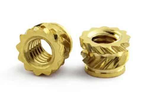
Here's the stepper side. 2 sets of 2 M3 bolts grip the shaft. They are held in place by hot melt inserts like these:
The hot melts are inserted into the print from the inside. By screwing the M3 bolt into the print, once the bolt hits the leadscrew it will drive the hot melts up into the print and provide tension on the shaft (limited by the ability of the plastic to keep it all together - admitteldy this print is a bit light around the bolts(


These two parts are interfaced by the middle part of the oldham coupler (not shown - check out thingiverse). I had to fiddle a bit till I was happy with it: sand it down so the parts move smoothly but aren't loose and then coat interfaces with some white lithium grease. Finally, I dragged the laptop out to the garage


And it was time for a test:


Which was pretty awesome! When I tightened up the dovetails to eliminate backlash/play, though, the motor started slipping in its coupling. I will need to make this part out of aluminum and tap holes for the set screws. I'm pretty confident the other parts can remain plastic as long as I need them to.

Next up... y-axis!

Saturday, October 7, 2017

Electronics

I bought electronics for the conversion this summer. But of course other things got in the way. Assuming you have a little experience with Arduino and electronics this is more or less childs' play but even if you are a novice it is not all that hard to learn.

The first thing I had to decide on was how I wanted to talk to the CNC mill once it was built. There are two major ways that I know of. The first is LinuxCNC, which is comprehensive and has lots of features. Essentially it is a layer of software you install on top of your Linux OS. It is built to utilize high end controllers (like PCI/ISA cards, parallel port and ethernet interfaced industrial controllers, etc.) Having direct access to the hardware like this means they can do a lot of cool things, but the price barrier was higher than I liked. Cheap mill, cheap electronics! 

I decided to go with an Arduino based GRBL board. This board is an Arduino shield which interfaces four stepper motors along with end stop switches to the computer via USB. The firmware you compile and upload to the Arduino accepts gcode and then actuates the steppers per the gcode. The paradigm is exactly like that of a 3D printer. Definitely get one with the DRV8825 chip that is rated to a higher voltage/amperage.

For a power supply I picked this one which is variable 0-48v with a built in potentiometer. It also includes a second potentiometer and header so you can use an arbitrary length of wire to mount the pot wherever you like. The integrated display is a neat feature, it lags and is off by a few tenths of a volt but handy nonetheless. Nice thing about a variable supply is you can test at a lower voltage and then when you work with materials increase the voltage as high as you need. 

The steppers I picked up off of eBay are NEMA 23's with dual shaft. Do note that not all NEMA steppers are alike: be sure to look at the torque rating! 2.83 Nm (or in God's Units, 400 oz-in) is plenty but you will find many NEMA 23's rated at a fraction of that value. One of my requirements was to find a way to keep the handles on the mill for small manual jobs. Truth be told after some more thinking I really only needed one of these to be dual shaft (the Y axis) so you can potentially save a few bucks buying one dual shaft and two non-dual shaft. But trust me on the torque.

Eventually you will want end stops. These leaf switches are set up to trigger near end of travel and will cause the GRBL board to stop sending signals which would overdrive your machine. But for initial setup and testing, unnecessary. If you don't have them you will need connectors (0.1" header female) to connect the steppers to the board (I had spares aplenty from my 3d printer). And a computer of course. For testing your laptop is just fine. For the permanent install I will either use a Raspbery Pi with Octoprint (there is a GRBL plugin!) Octoprint is a 3D print server which allows you to upload your gcode over the network and it will stream the code to the device. 

So last night I wired up the stepper. Fortunately the auction had a schematic with wire colors but it isn't impossible to figure it out by trial and error. We are interested in "bipolar series" wiring since we have eight wires but only four connectors. On these steppers there are two pairs of two phases, and you wire them in series. 


Then you need to compile and upload grbl to the arduino. It is not as intimidating as it sounds, the step-by-step instructions are very clear. Once the firmware is uploaded put the shield on, connect power at 12v (lowest operating voltage) and connect the motor. Test wiring complete!

Now we need code to drive the steppers. The one I used is grblPanel. Grab the latest release and double-click the executable. Set the port to the COM port where your Arduino is and if all is well click (+X) and watch your stepper step! 

Sunday, October 1, 2017

Mill tear-down

So Robothon was yesterday. My metal combat bots were both 0-2 but neither was demolished; in fact they both still run. The next competition is at the end of January at the Northwest Model Hobby Expo, so I have a solid 3 months and some change to finish the conversion. 

Today I stripped down the table of my mini mill, because the y-axis has always been particularly sloppy ever since I got it. And I figure I should start with a clean, dialed-in machine. After cleaning chips and wiping down the machine I took off the x-axis by spinning the table all the way to the right and then taking off the handle and key. By jamming the table left to right a few times I was able to free the outer bearing and remove the table. The last bearing I took off by placing a crescent wrench against the bearing and then tapping it with a rubber mallet. Now the Y axis is exposed and the culprit became immediately apparent: the nut on the leadscrew is free floating in a slot in the y-axis table and is supposed to be pinned in place by a screw which was loose. Screwing it down and tightening the handle, the slop was instantly gone. Great, but I proceeded to finish stripping it down to clean and oil. Once the table was off I discovered the column was not properly aligned:


I loosened the outer two bolts and took a half-turn off of the center bolt and was able to rotate the column to visual alignment - once I have the table rebuilt I'll use an indicator on a magnetic base to confirm proper alignment. 

I cleaned off all of the packing grease I could find and rubbed everything down with an oily cloth and reassembled the y-axis. I tightened the screw which pins the leadscrew nut and tightened the nut on the handle to a comfortable tension and there was no visible play in the bed - of course once fully assembled I'll verify with an indicator. 


Tomorrow night I'll assemble the x-axis and work on confirming things are nice, smooth and aligned.

Saturday, September 30, 2017

3D printed soft jaws

So I've been a little slow to make progress on the CNC conversion. Besides work ramping up and kids' evening sports I've been occupied by building combat robots. Here's my 3 pound bot, Love Hate Love (left) inspired by my 1lb plastic bot, Rain When I Die:


If you sense a theme in the names, it's the song playing when I go to hit "Save" on the CAD file, and I've been on an Alice in Chains kick as of late.

In the process of making hubs for the wheels, I needed a pair of soft jaws. I have two 3D printers so I whipped a set up in CAD and printed them off. I added them to Thingiverse. Here's what they look like on the lathe:

They are printed with ABS at 100% infill. I don't expect them to last terribly long but they work well for touching up parts and surface finish passes. I plan on printing a pair in Nylon in the near future. 

Tuesday, July 11, 2017

Harbor Freight CNC

This blog will document the conversion of a Harbor Freight Mini Mill into a full CNC machine on the cheap. My application is combat robotics. What's yours?

more successes

Next thing to do was cut something with multiple depths. Eventually I'd like to make some keychains for gifts and myself and family (wel...